During my firewall forward modifications I ran in to a bit of a problem. For starters, remember this engine is 34.25″ wide compared to the original O-360 that is about 33.25″ at the center of the valve cover. So, combine the wider engine with the bigger angle valve heads and the cowling becomes very complicated. During the initial planning of the new cowling project it quickly became clear that the original factory engine offset was going to cause me some serious problems. Let me start by explaining what the offset was originally all about without going in to a ton of detail.
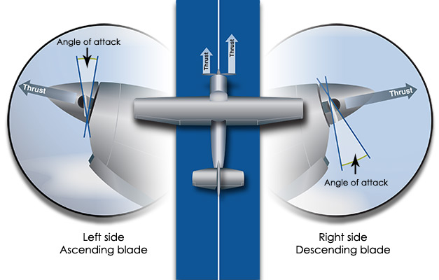
In most GA (General Aviation) airplanes the engine is angled to the right to accomplish a few things. Mainly it helps compensate for P-factor. P-factor is caused by a dissimilar amount of thrust generated by the propeller. This happens when the airplane is at a high angle of attack such as takeoff. The descending blade has a higher angle of attack and therefore generates more thrust, yawing the airplane to the left. (with an engine that rotates clockwise that is) The corrective action being, use right rudder to coordinate the airplane. This image from the AOPA explains it pretty well:
Another reason for the engine to be offset is to help tame stall characteristics. When the airplane is stalled, even at idle power, it requires the airplane be coordinated so it stalls straight ahead. The FAA has defined a standard for certified airplanes in this regard. To meet those standards, the engine offset is required.
So, I can sum this up pretty quickly. Use the damn rudder! It’s not just for taxing out.
Now I can get specific in regards to Unleashed. The first down side to having this offset is it causes your propeller to have an incorrect angle of attack for the majority of your flight conditions: Straight and Level. In a Cessna the cruises 30 kts more than it climbs, who really cares. But in a Lancair that cruises (or races) 100-130 kts over its initial climb speed, then you have issues. The envelope is so much bigger. I spend 95% of my time in the top 25% of its speed range so I fail to justify a correction for that bottom end of the envelope. I do not stall this airplane and I seriously doubt the engine angle would make that any better anyway. The second down side to this offset is simple. The engine won’t fit in the cowl, and the spinner (with the prop extension) would be noticeably off center.
When discussing this subject with the locals (RV guys, that all have an offset) I was given many opinions, all of which agreed it would be a bad thing to mount the engine straight. Anything from torque effects, to how gyroscopic procession would yaw the airplane, etc.. Moral of the story, I again defied their advice, and it flys great! There are many high performance airplanes that all have their engines mounted straight and level. Turbine Legend, Radial Rocket, NXT, etc.. If there is a yaw problem under power, the vertical surface isn’t big enough, end of story.
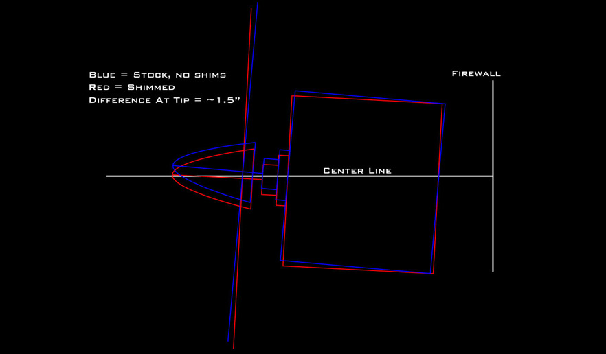
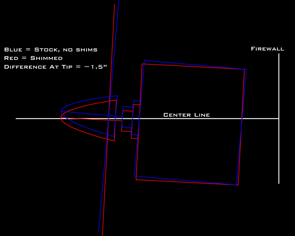
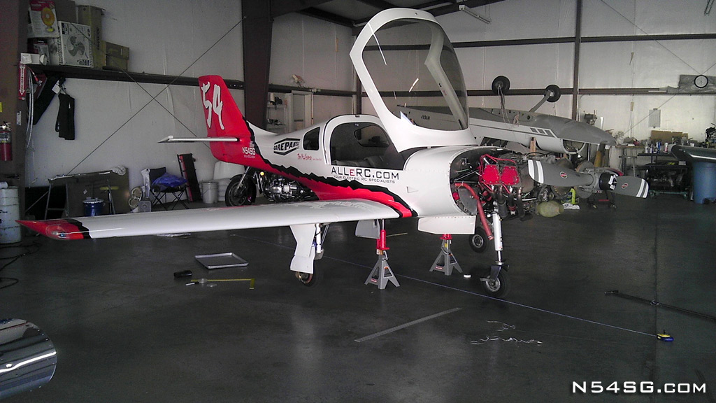
In fear of this getting any longer, I should probably get to the point. The original engine offset was designed into the engine mount. Rather than just pointing it to the right, they offset the aft of the engine to the left of the center-line. Thus, the spinner was still in the middle of the cowl, sort of, while the engine was pointed to the right. When I added my prop extension of 2.25″ it compounded the problem. The tip of the spinner was 1.75″ to the right of the center-line of the airplane.
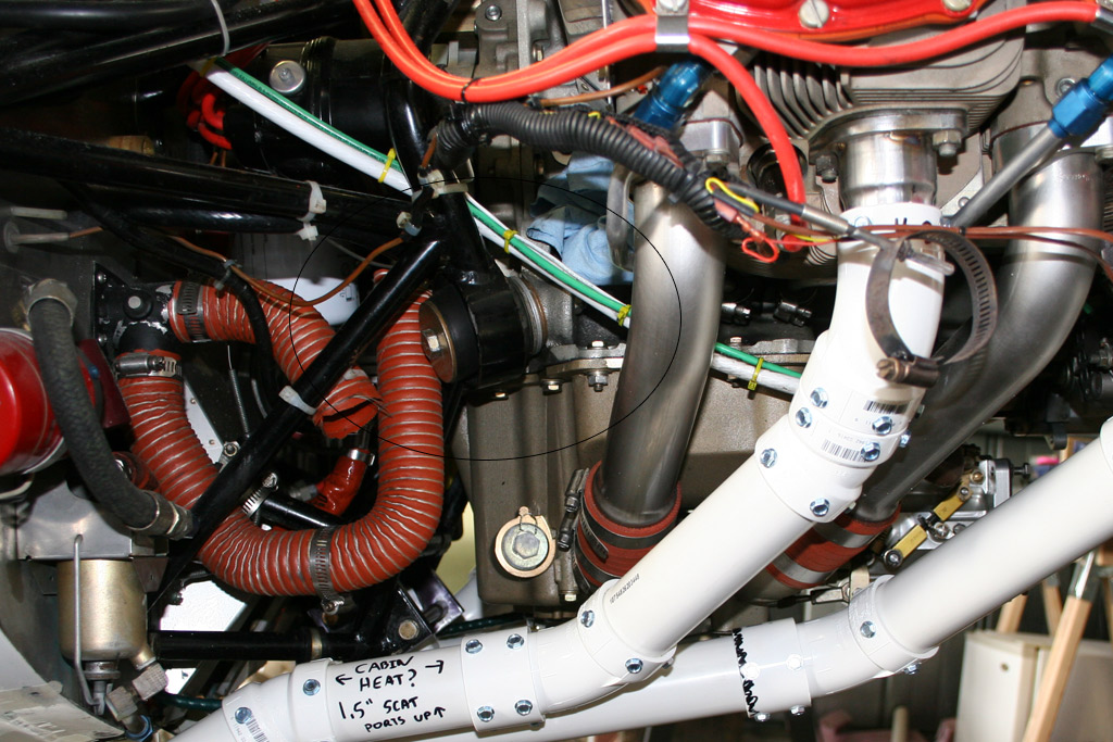
I could not correct this with spacers on the firewall because of the nose gear. It pivots on the engine mount and must maintain its center. So, I added spacers on the dynafocal mounts. I had already shimmed the engine in pitch once before. 2 washers (.25″ total shim) on the bottom mounts leveled the engine in pitch. To turn the engine to the left, it would require 2 washers on both the right side mounts. So, the bottom right mount actually has 4 washers installed. (circled in the picture to the right) In the end, the tip of the spinner landed within .25″ of center-line, and the valve covers were inside the width of the firewall so the cowl wouldn’t require any “cheeks”. A truly centered angle is impossible with this mount, but I’m close. I’d call that a win.
The local EAA Chapter 91 allowed me to use their hanger floor to establish a good centerline. My hanger is far from level, so this helped a ton. I dropped a plumb bob from the tie down hole at the tail, and the center of the firewall with the airplane level. Then I could extend the centerline out past the propeller.
So with all this being said, and having flown it both before and after the angle change, its great! During the Reno Air Races, I flew the same small fixed trim tab I have always flown, a Bic pen under some electrical tape. It was almost perfect and required hardly any rudder input on the track. The only noticeable difference is the required rudder on takeoff. But, it isn’t out of line, and the faster you go the better it gets. You can’t cram in 230 hp from a dead stop on the runway and expect it to go straight. It takes gradual power input with full right rudder. As speed builds the vertical starts working, and the required rudder reduces until you establish a climb. In the end, just keep it coordinated like you always should in any airplane.

I agree. You are awesome and so is Unleashed.